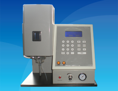
Flame Photometer
model: TR-FP5301
Standard:
E-mail: robin@pro-trueview.com
Working Principles
According to the molecular structure theory, outer electrons of atoms always move via a trapped orbit, which they usually move out of and transit to the orbit of the excited level, if they receive the heat energy provided by a flame. At the same time, attracted by the nucleus and recovering from the excited level to the normal level, the electrons release energy which can be illustrated by the spectra that release specific wavelengths. This method, which measures the luminescence levels of the elements to be determined at specific wavelengths through qualitative and quantitative analyses, is called analysis of spectra based on flame emission, and the instrument which applies to this method is called a flame photometer.
Theoretically, the contents of the elements to be determined are proportional to the intensity of the spectra released; however, the flame photometer normally applies only to the quantitative analysis of some alkali metals and alkaline earth metals at a certain concentration range, as limited by the excitement energy.
Applications
1. Analysis and measurement of cement, glass, ceramics and heat-resisting materials.
2. Measurement of the agricultural land survey and total nitrogen contents of soil.
3. Product analysis and monitoring in pharmaceutical industry and food industry
4. Content analysis of potassium and sodium in serum and urine in clinical treatment.
Main Technical Specifications
1. Receiving elements: silicon photocells
2. Spectrophotometry method: interference colored filters
3. Displaying method: liquid crystal displayed readings
4. Stability: Users keep sampling with standard solutions. The maximum relative variation displayed in the instrument is not greater than 3℅ in 15s, with 1 measurement every minute, and the total measurement is 6. All the variations displayed in the instrument should be not greater than 15℅
5. Repeatability: ≤3℅
6. Linear Error: K: ≤0.005mmol∕L
Na: ≤mmol∕L
7. Response time:<8s
8. Suction jet of samples:<6mL∕min
9. Measuring Range:
Na: 0 - 100ppm; K: 0 - 100ppm; Li: 0 - 100ppm; Ca: 0-1000ppm;
Ba: 0 - 3000ppm;
1) Measuring Limit:
Na: 0.01ppm; K: 0.01ppm; Li: 0.025ppm; Ca: 0.1ppm;
Ba: 10ppm;
2) Constructional features:
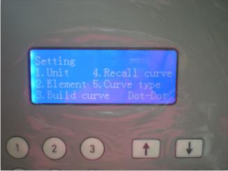
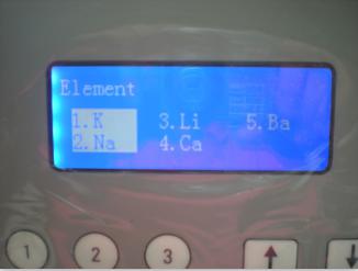
a) Able to detect 5 filters with Na, K, Li, Ca, Ba, 5 channels; displays 3 elements and their contents;
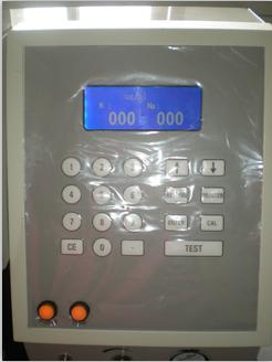
b) a touch panel with a digital keyboard;
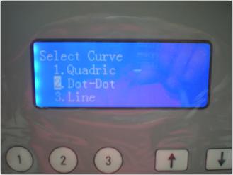
c) single point corrections -- the correction curve can be saved on the instrument;
d) Interface RS232, through which computers and printers can be connected;
e) a mist separator;
Specifications
| Model | TR-FP1600 | TR-FP1501 | TR-FP1502 | TR-FP5301 | TR-FP 5302 | TR-FP2200 |
|
Measure Range (ppm) |
K: 0-100 Na:0-100 Li: 0-100 Ca:0-1000 Ba:0-3000 |
K: 0-100 Na: 0-100 Li: 0-100 Ca: 0-1000 |
K: 0-100 Na: 0-100 Li: 0-100 Ba: 0-3000 |
K: 0-100Na: 0-100 Li: 0-100 |
K: 0-100 Na: 0-100 Ca: 0-1000 |
K: 0-100 Na: 0-100 |
|
Measure Limit (ppm) |
K: 0.01; Na: 0.01; Li: 0.025; Ca: 0.1; Ba: 10; |
K: 0.01; Na: 0.01; Li: 0.025; Ca: 0.1; |
K: 0.01 Na: 0.01 Li: 0.025 Ba: 10 |
K: 0.01Na: 0.01Li: 0.025 |
K: 0.01 Na: 0.01 Ca: 0.1 |
K: 0.01 Na: 0.01 |
| Drift | ≤ 3% (after 30 minutes when the instrument stability) | |||||
| Sample Rate | 4 ~ 6ml/min | |||||
| Linearity | Better than the best results of the intermediate value of 2% (single-point CAL) | |||||
| Response Time | ≤8s | |||||
| Time Stability | Less than 15 seconds (when the sample was taken after the flame | |||||
| Calibration Methods | Straight line, broken line, secondary fitting | |||||
| Size & Weight | 530*510*580mm & 27kg | |||||
| If you order, we will provide the professional printer or PC software for you freely ! | ||||||
Maintenance Notice
1. After each test, users keep instilling the distill water for 5 minutes to clean up the inside of the atomizer.
2. When pressure reducing valve for filtering of the air compressor works, water in the air is suppressed and condensed within it. This long-time standing water influences the normal operation of the instrument. Therefore, after using pressure reducing valve for filtering for a period of time (every week), users should lift the instrument and turn the left valve at the back. Pushed by the compressed air, standing water automatically releases. Users need to turn at the opposite direction when all the water is gone.
3. When the air compressor works, water in the air condenses at the bottom of the air compressor. This long-time standing water influences the normal operation of the instrument. After using for a certain period (every week), users should lift the air compressor, and turn the release valve beneath the air compressor. Pushed by the compressed air, standing water automatically releases. Users need to turn at the opposite direction when all the water is gone.
